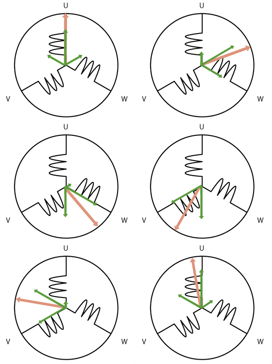
Like transformers, induction motors have a lot of inductance. This causes a lot of reactive lagging current to flow and makes the power factor very poor. The power company doesn't like this, so they charge large customers if their power factor is poor. This means it must be corrected. Recall in the Circuits Lab we had a small table top motor that we corrected the power factor on by adding parallel capacitors. High voltage, high value capacitors are a bit expensive, and it is even more expensive to switch them in and out of circuit as the power factor changes in a plant, so having a continuously variable reactance is interesting to users of large induction motors.
Synchronous Condenser
Condenser is another word for capacitor. These can be very large, and are really used in the real world.

A synchronous motor run without a load makes a very nice variable reactive power generator. It can replace a capacitor. Let's try and understand why this works by considering a lossless synchronous motor, which isn't a terrible approximation, because with a synchronous condenser, they often fill it with a Hydrogen atmosphere which reduces windage, and in general are made as lossless as possible. Recall that a synchronous machine has a rotating field created by three phase currents in the armature,

and a stator whose electromagnetic flux is adjusted by adjusting the DC field current in the stator winding, $I_f$. As with any motor there is a back EMF, $\hat E_{af}$ generated as a result of Faraday's and Lenz's laws. This is the AC that would be generated by the motor running as a generator. The circuit model for one phase of a synchronous motor is an inductance between the applied phase voltage and the generated voltage.
Since the motor is essentially lossless, we may ignore $R_a$, leaving us with $X_s$ only. The torque angle is essentially zero degrees, because there is no loss to keep the rotor slightly delayed from the rotating magnetic field. The magnitude of $|\hat E_{af}| = E_{af}$ can be increased by increasing the rotor's DC field current, $I_f$, because it increases the $\mathbf B$ and so the magnetic flux, $\phi$. $E_{af}$ can be increased to be greater than the magnitude of the applied voltage, $|\hat V_a| = V_a$, and can be decreased so it is less than $V_a$ easily by adjusting $I_f$. Because the torque angle is zero, the angle of the generated voltage, $\angle \hat E_{af} = \angle \hat V_a$. When $\hat E_{af}$ is adjusted so $\hat E_{af} = \hat V_a$, the current $\hat I_a = 0$. This gives us a zero power out or in. When $E_{af}$ is increased, the current $\hat I_a$ is coming out of the synchronous condenser the opposite way the figure shows it above. Furthermore, only VARs are produced (no watts), because there is no real power generated or lost by this "lossless" machine. Since $X_s$ is inductive, and the current switched directions it makes a current that would be produced normally by a capacitor (leading, not lagging as it would in an inductor normally), making the synchronous machine appear as a capacitor. The amount of VARs produced can be adjusted by changing the DC field current, $I_f$. Likewise if you reduce the DC field current, you will not swap the direction of the armature current $\hat I_a$, and you will have a lagging power factor. In real life there are some losses, but real curves show the same behavior, because the losses are small. Here is a real set of curves.
The lowest curve is the one to look at, as it is running there as a synchronous condenser (no mechanical load). As you see, you can run a motor that you wish to use as a loaded motor too, not just as a synchronous capacitor (unloaded) and still correct the power factor, and in this case the power dumped into the motor is not zero at all, but you still see how the power factor can still be adjusted. Note how the minimum current occurs when the power factor is corrected to unity. If you are running in parallel an induction motor, you will want to adjust your synchronous capacitor to an over excited state (leading or capacitor mode).
Questions
- Why does it make a capacitor into an inductor when you change from a motor to a generator?
- How do you remember leading means a capacitor, not an inductor?
- Why is the torque angle zero in a synchronous condenser?
- Why is the armature current, $\hat I_a$ perpendicular to $\hat V_a$ in a synchronous condenser?
- Can a generator generate mostly VARs, and very few watts?